Computational Fluid Dynamics Analysis of a High-Power COB LED Array
Abstract
This study focuses on the thermal analysis of a high-power Chip-on-Board (COB) LED array, designed for horticultural applications. The primary objectives are to evaluate the effectiveness of different thermal management techniques and to assess the overall thermal performance of the system under specified operating conditions. The analysis was conducted using SolidWorks 2023 Flow Simulation software. Two scenarios were investigated: (1) Open-Air Active CPU-Cooler Heatsink Configuration, and (2) Open-Air Passive Pin-Fin Heatsink Configuration. The results indicate that the conventional method of cooling COBs with passive pin-fin heatsinks is ineffective.
1 Introduction
This report presents a Computational Fluid Dynamics (CFD) analysis of a novel horticultural lighting system based on a high-power COB LED array. This study focuses on the thermal performance of the system, specifically evaluating the effectiveness of conventional passive pin-fin heatsinks versus active CPU-coolers.
2 Methodology
The thermal analysis was performed using SolidWorks 2023 Flow Simulation software. A refined mesh was employed to ensure the accuracy of the results. The simulations were conducted under the assumption of standard ambient atmospheric conditions, with an atmospheric pressure of 101,325 Pa and an ambient temperature of 25 °C.
2.1 Material Properties
The heat sink and heat pipes of the Scythe Fuma 3 cooler (used in the active cooling scenario) are constructed from aluminum, while the baseplate is made of copper. The relevant thermal properties of these materials are listed below:
| Property | Aluminum | Copper |
|---|---|---|
| Thermal Conductivity (W/m/K) | 237 | 401 |
| Specific Heat Capacity (J/g/K) | 0.897 | 0.385 |
| Density (g/cm³) | 2.70 | 8.96 |
| Thermal Expansion Coefficient (µm/m/K) | 23.1 | 16.5 |
2.2 System Setup and Boundary Conditions
Each COB LED has a maximum power consumption of approximately 53 W. To ensure efficient heat transfer, a thermal interface material (TIM) with a thermal conductivity of 15.2 W/m/K (Frost X45 thermal paste) is used to mount each COB to a thin copper interface plate. This assembly is then directly mounted to the cooler.
Two primary scenarios were investigated:
- Scenario 1: Open-Air Active CPU-Cooler: The COB LED array was simulated without an enclosure, representing an open-air environment and utilizing active cooling with Scythe Fuma 3 CPU coolers, equipped with Kaze Flex II PWM fans (25 mm) operating at a maximum speed of 1400 rpm. The initial temperature of the heat sinks was set to 42.5 °C.
- Scenario 2: Open-Air Passive Pin-Fin Heatsinks: The COB LED array was simulated without an enclosure, representing an open-air environment and utilizing passive cooling with pin-fin heatsinks. The pin-fin heatsinks have the following dimensions: diameter: 135 mm, overall height: 70 mm, base plate thickness: 10 mm. The array consists of 61 LEDs.
2.3 Assumptions
- The system operates under steady-state conditions after an initial transient period.
- Heat generation in each COB LED is directly related to its input power and is assumed to be uniform across the COB surface.
- Airflow is assumed to be laminar.
- Heat transfer through radiation is considered negligible compared to convection and conduction in the active cooling scenario, *but is considered in the passive cooling scenario*.
- Uniform Heat Generation: The 53 W heat load was assumed to be uniformly distributed across each of the 61 LEDs.
- Material Properties: Constant material properties (thermal conductivity, specific heat, density) were assumed.
3 Results and Discussion
3.1 Scenario 1: Open-Air Active CPU-Cooler
This analysis focused on the thermal performance of a single COB LED and CPU cooler assembly.
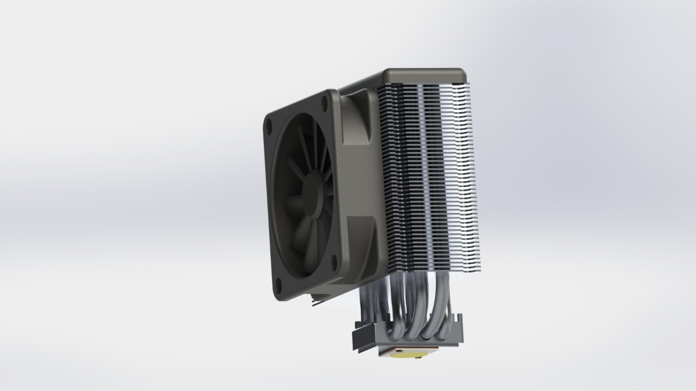
Figure 1: CFD Results - Single COB LED and CPU-Cooler Assembly (Solid Temperature).
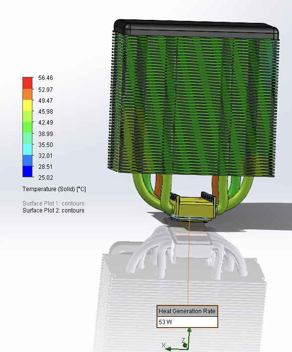
Figure 1: CFD Results - Single COB LED and CPU-Cooler Assembly (Solid Temperature).
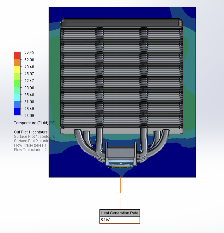
Figure 2: CFD Results - Single COB LED and CPU-Cooler Assembly (Fluid Temperature).
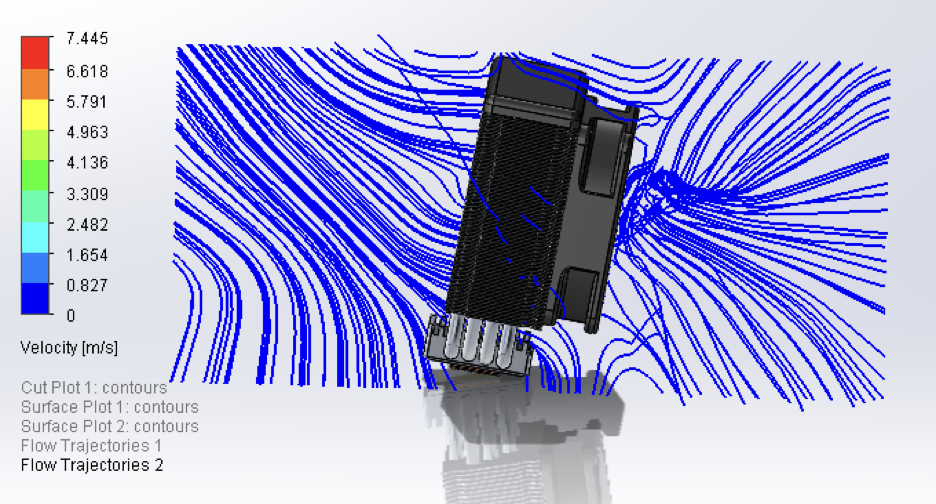
Figure 3: CFD Results - Single COB LED and CPU-Cooler Assembly (Airflow).
The temperature distribution demonstrates that the cooler effectively dissipates heat. The maximum temperature observed on the solid components is 56.45°C, while the minimum fluid temperature is 24.99°C. The majority of the heat sink surface area exhibits a temperature of approximately 42.5°C. The airflow simulation reveals that the highest air velocities, reaching up to 7.445 m/s, are concentrated near the heat sink fins.
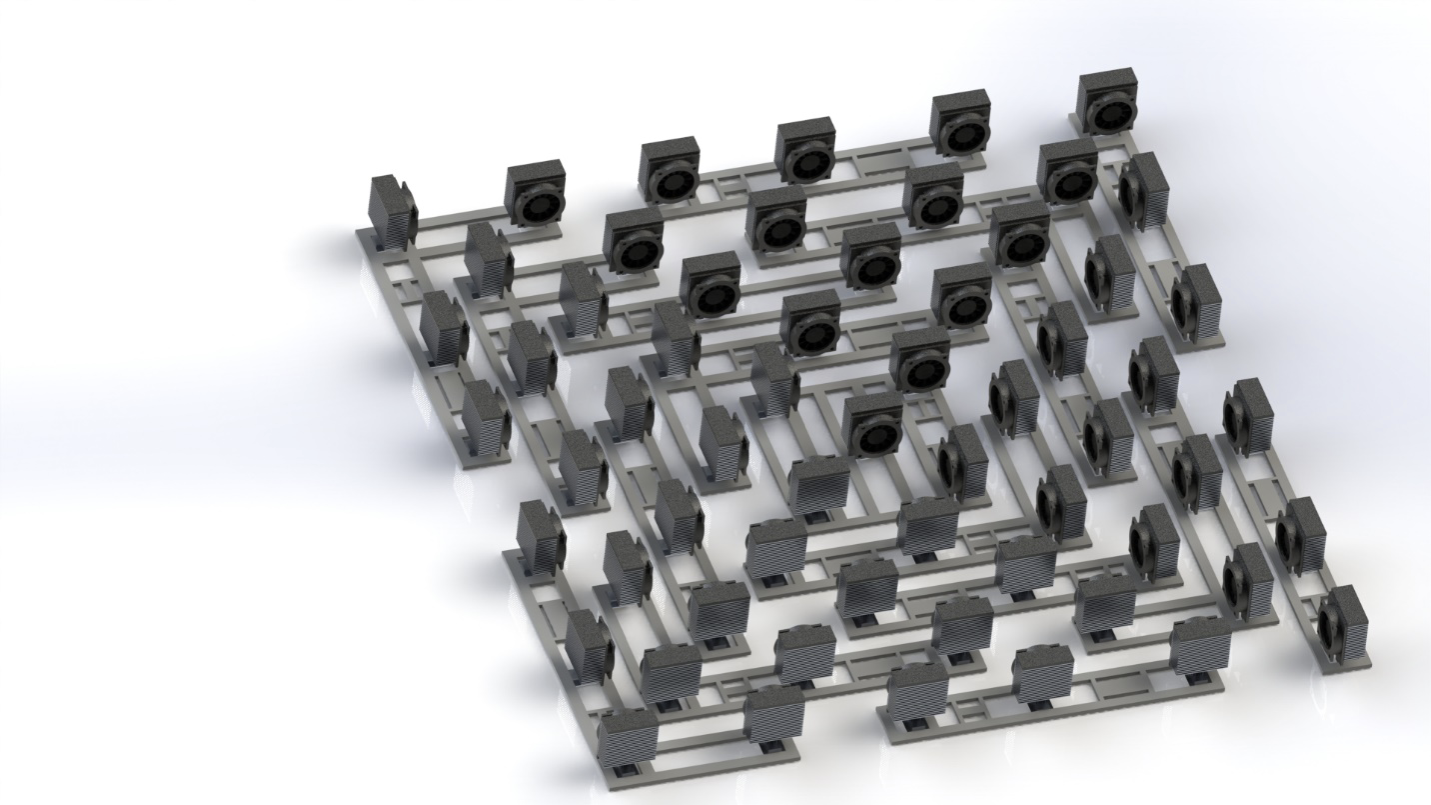
Figure 4: Open-Air Active Cooling - Full Array
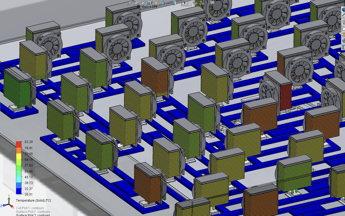
Figure 4: Open-Air Active Cooling, Solid Temperature
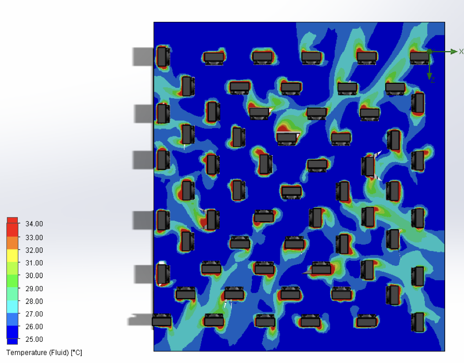
Figure 5: Open-Air Active Cooling, Fluid Temperature
| Scenario | Max. Temp. (°C) | Avg. Temp. (°C) | Min. Temp. (°C) |
|---|---|---|---|
| Active (Single) | 56.45 | 42.5 | 24.99 |
| Active (Array) | 100.43 | 62.48 | 25.19 |
3.2 Scenario 2: Open-Air Passive Pin-Fin Heatsinks
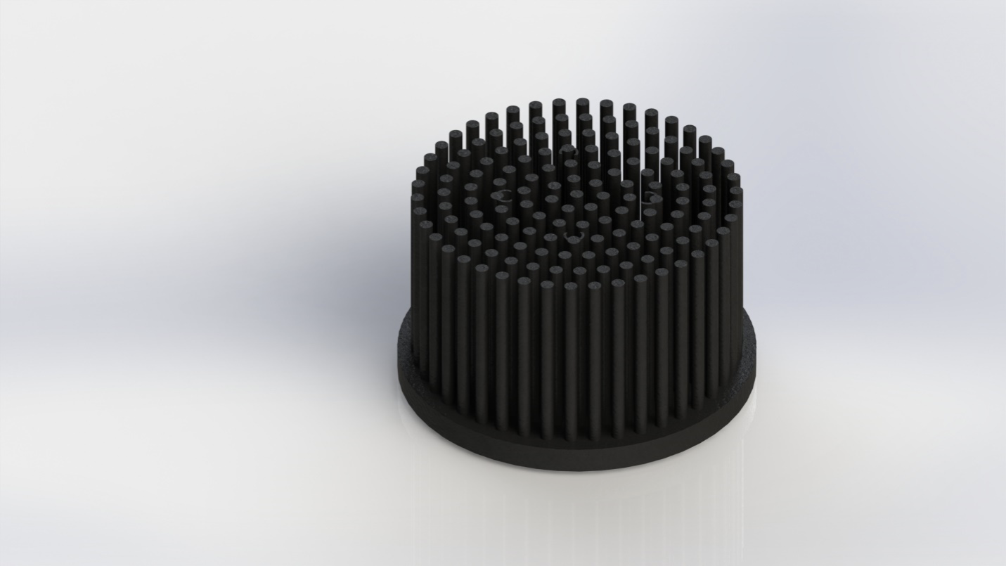
Figure 6: CFD Results - Passive Pin-Fin Heatsink (Single).
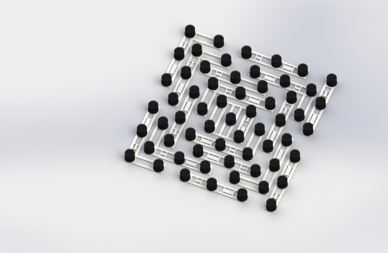
Figure 7: CFD Results - Passive Pin-Fin Heatsink Array
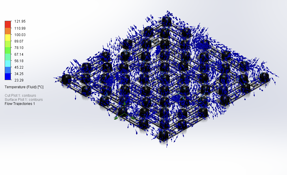
Figure 8: Passive Cooling Air Temperature Distribution
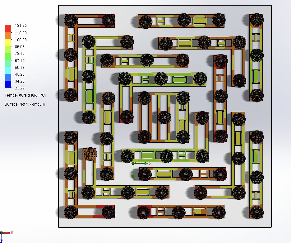
Figure 9: Passive Cooling Solid Temperature
The simulation indicates a maximum air temperature of 121.95 °C in localized regions. A large portion of the domain exhibits an average air temperature of approximately 34.25 °C. The maximum solid temperature significantly exceeds typical safe operating temperatures for LEDs.
| Scenario | Max. Temp. (°C) | Avg. Temp. (°C) | Min. Temp. (°C) |
|---|---|---|---|
| Passive (Array) | 122.24 | 102.24 | 40.05 |
The CFD analysis demonstrates that the active cooling solution with CPU coolers provides significantly better thermal performance than the passive pin-fin heatsink solution. The passive cooling solution results in unacceptably high temperatures, exceeding the safe operating limits for the LEDs.
4 Conclusion
The CFD analysis of the passive pin fin heat sink, under the specified conditions, demonstrates inadequate cooling performance for the high-power COB-LED array. The predicted maximum solid temperatures are significantly above acceptable operating limits, indicating a high risk of LED failure or performance degradation. This result highlights the need for a more effective thermal management solution, such as forced convection (using fans) or a more advanced heat sink design (e.g., with a larger surface area or a different fin geometry), or a combination of these. The comparison with other cooling methods further reinforces this conclusion. Future work should include experimental validation of these simulation results and explore alternative cooling strategies. The inclusion of radiative heat transfer in future simulations is also recommended.

