WHY RADIANCE

Horticulture Lighting Simulator, Powered by Radiance

A lighting engine chosen for physics, not convenience.

Luminous Photonics uses Radiance to calculate how light moves through modeled horticultural environments, then transforms those transport results into spatial, spectral, and plant-level insight.

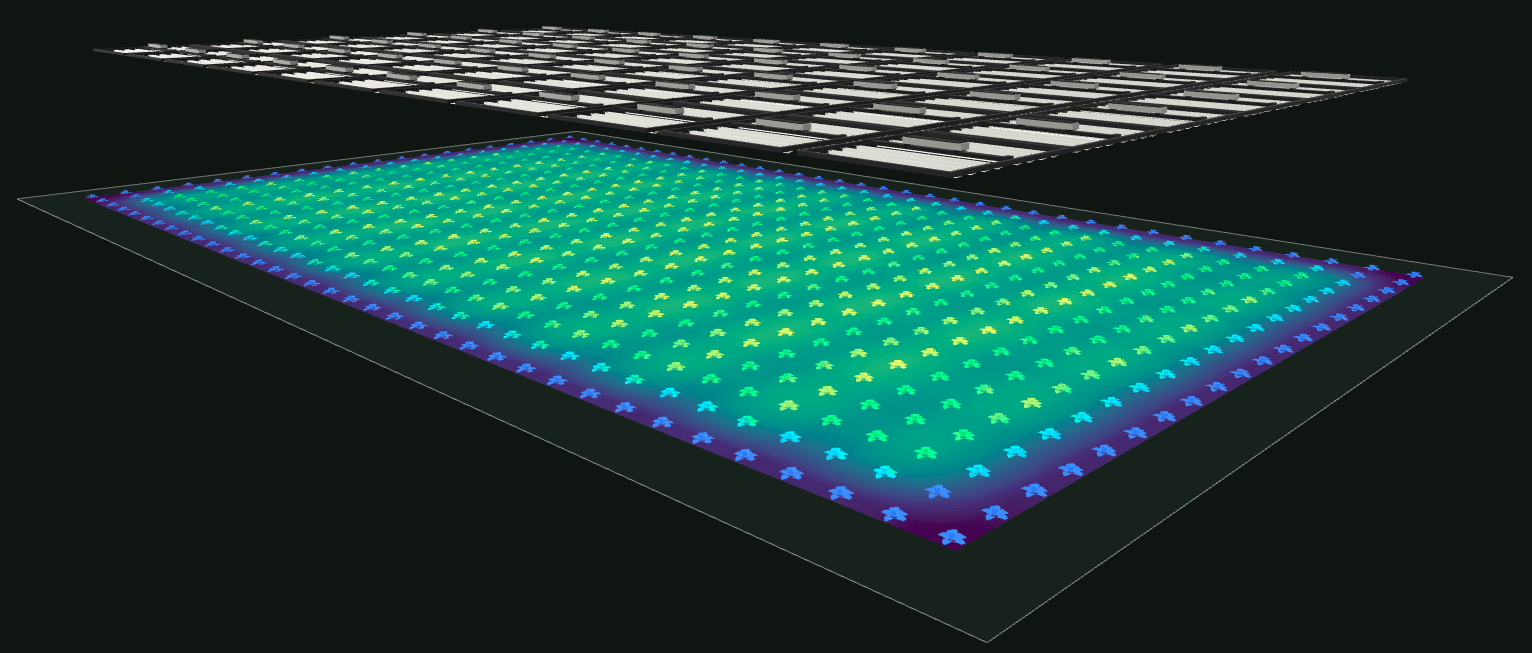
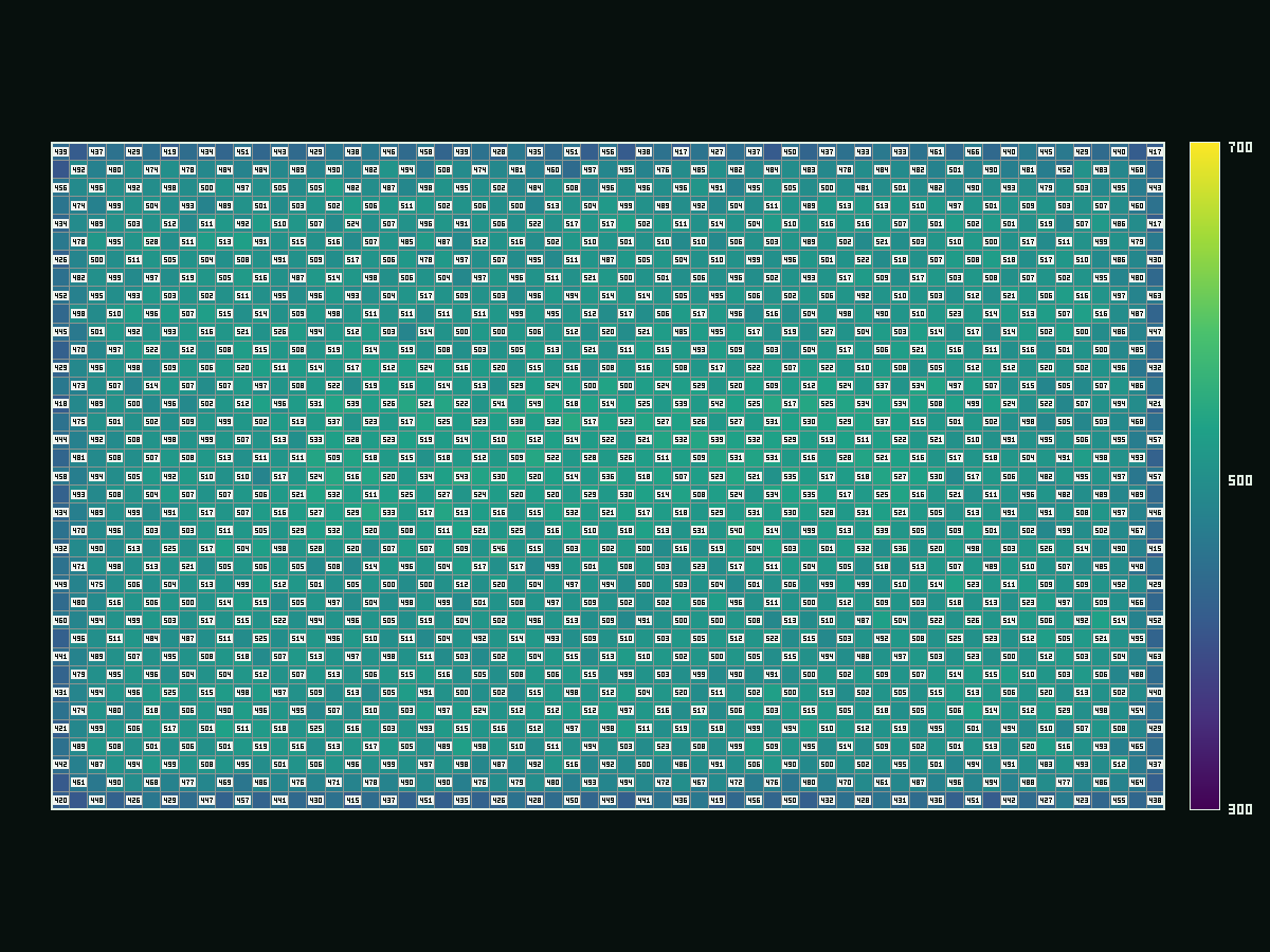
Modularized LED Lighting System
30 FT × 50 FT
Perspective view of a 30 ft × 50 ft Modularized LED Lighting System above plant geometry colored by modeled surface flux.
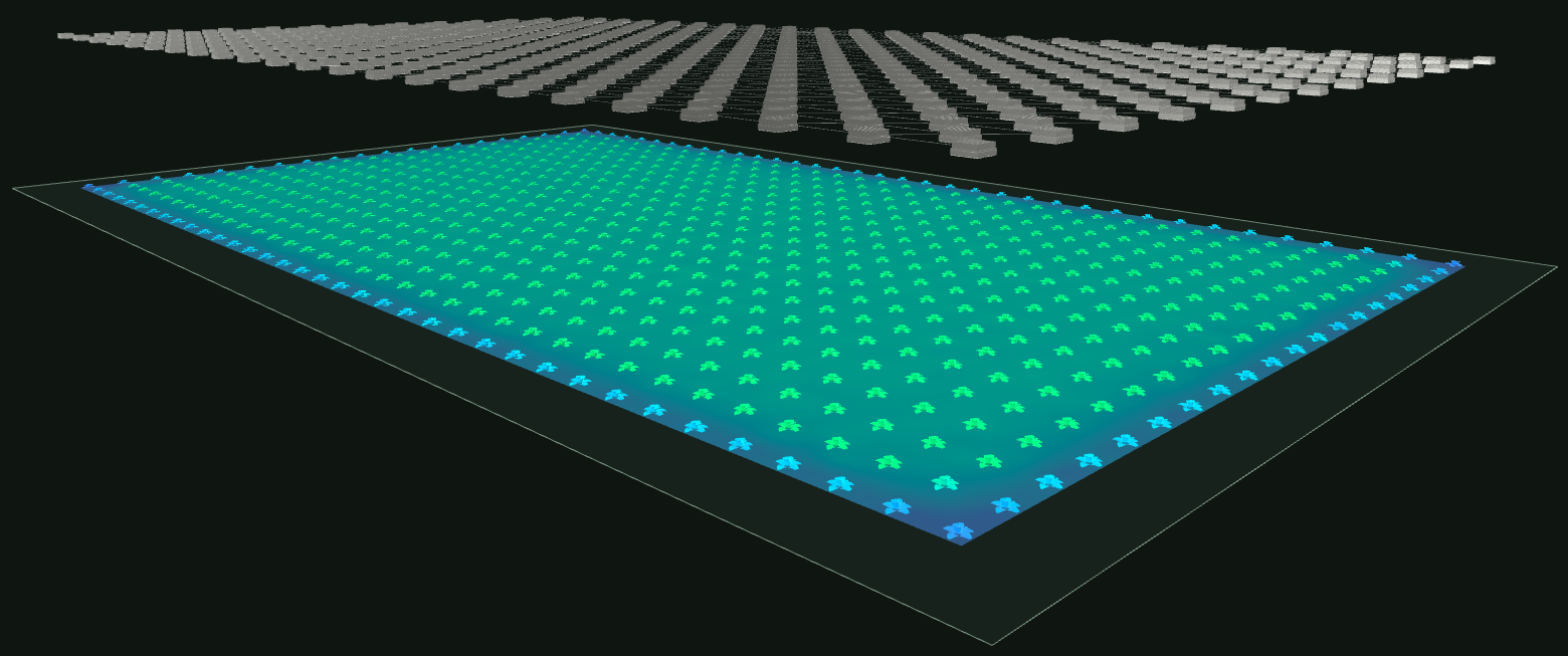
Conventional LED Lighting System
30 FT × 50 FT
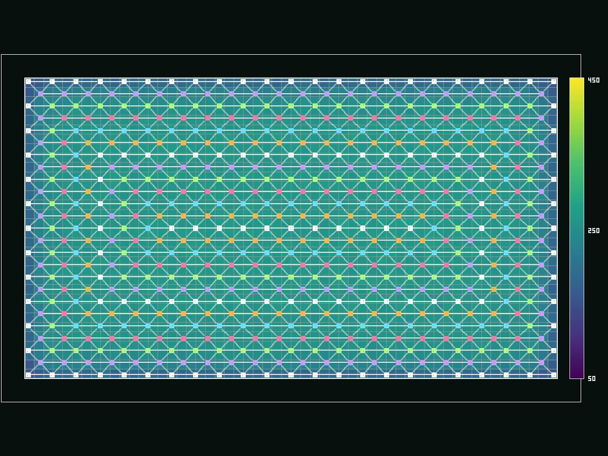
Perspective view of a 30 ft × 50 ft Conventional LED Lighting System above plant geometry colored by modeled surface flux.

PHYSICAL FOUNDATION

Why Radiance

The simulator needs an engine that treats geometry, sources, materials, visibility, and interreflection as one transport problem. Radiance provides that physical foundation and a toolchain that can be composed around a specialized horticultural application. 12

Three evidence channels aligned for validationCalculation, scale-model, and real-space evidence channels converge into a structured comparison grid.CALCULATIONSCALE MODELREAL SPACECOMPARISON GRID

Validated foundation

One of the most rigorously validated lighting simulation engines. 1

Radiance has been compared with lighting calculations, scale models, and real spaces. Its documented method separates direct, specular-indirect, and diffuse-indirect contributions within a physically based, light-backwards ray-tracing system. 12

Open source code feeding permitted capabilitiesA Radiance source-code document connects to use, modify, and redistribute capability modules.RADIANCE / SRCUSEMODIFYREDISTRIBUTE

Open by design

Radiance is distributed as source code under a license that permits use, redistribution, and modification. That openness makes the transport foundation inspectable and keeps the simulator from depending on a sealed lighting engine. 4

Composable Radiance processing pipelineFive adjacent nodes present scene, oconv, rtrace, data, and the emphasized domain user interface in left-to-right order.SCENEOCONVRTRACEDATADOMAIN UI

Built for composition

Radiance is a collection of programs designed to work in concert. Scene conversion, transport, filtering, analysis, and domain-specific interfaces can remain distinct, which is exactly the boundary the simulator needs. 3

Radiance's published validation history supports the core lighting engine. It does not by itself validate Luminous Photonics fixture hardware, plant optics, electrical input, or prototype equivalence.

TRANSPORT PROVENANCE

From Radiance to insight

Radiance performs optical transport. Luminous Photonics defines the domain inputs, retains transport artifacts, and turns those artifacts into horticultural views and metrics.

  1. LUMINOUS PHOTONICS IMPLEMENTATION

    Scene geometry, sources, and materials

    Room surfaces, fixture bodies, emitting faces, materials, plant geometry when required, and receiver definitions establish the declared scene.

  2. RADIANCE

    Radiance transport

    Radiance evaluates visibility and direct and indirect transport through the declared geometry, source, and material system.

  3. TRANSPORT OUTPUT

    Receiver and surface-flux artifacts

    Plant-free canopy-plane samples or plant-inclusive, banded leaf-surface samples preserve the transport result before presentation.

    • B
    • G
    • O
    • R
    • FR
  4. LUMINOUS PHOTONICS IMPLEMENTATION

    Simulator application layer

    The application aggregates receiver data, applies declared spectral profiles and units, and prepares spatial and plant-level result structures.

  5. LUMINOUS PHOTONICS IMPLEMENTATION

    Visualizations and metrics

    Heatmaps, raw-sample scatter views, fixture overlays, uniformity summaries, and leaf-level modeled photon flux make the result inspectable.

TWO-LAYER ARCHITECTURE

First, establish the room. Then, trace what reaches the plant.

The simulator separates the plant-free baseline from plant-inclusive receiver transport. This keeps canopy-plane PPFD artifacts independent of plant geometry while allowing a second layer to model transport at leaf surfaces.

LAYER 01

Baseline PPFD and uniformity

Scene
Room and fixtures
Receiver
Horizontal canopy grid
Transport basis
Scalar PAR PPFD
Outputs
Heatmaps, metrics, fixture overlays

Plant geometry: not included

LAYER 02

FSPM receiver transport

Scene
Room, fixtures, and plants
Receiver
Leaf-surface receiver samples
Transport basis
Multispectral B / G / O / R / FR
Outputs
Incident flux, modeled spectral absorption, reflection, transmission

Plant geometry: included

Transport architecture layers
LayerSceneReceiverTransport basisOutputs
Baseline PPFD and uniformityRoom and fixturesHorizontal canopy gridScalar PAR PPFDHeatmaps, metrics, fixture overlays
FSPM receiver transportRoom, fixtures, and plantsLeaf-surface receiver samplesMultispectral B / G / O / R / FRIncident flux, modeled spectral absorption, reflection, transmission
LUMINOUS PHOTONICS IMPLEMENTATION

Baseline PPFD artifacts remain plant-free. The FSPM scene contains plant geometry and declared leaf optical properties.

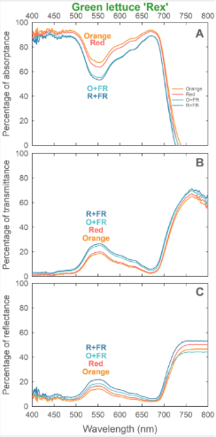
Digitized curves from Kang and Zhen (2025) are integrated into five transport bands: B, G, O, R, and FR. Profile-weighted absorptance, transmittance, and reflectance coefficients define the Rex leaf optical profile for each band. 6

Banded A/T/R coefficientsRex diffuse-transmissive Radiance trans materialplant-inclusive five-band receiver transportmodeled spectral absorbed, reflected, and transmitted photon flux

The pipeline describes Luminous Photonics' model construction. Reference 6 is the source of the digitized Rex curves, not a validation of the simulator implementation.

Three plots of Rex lettuce leaf absorptance, transmittance, and reflectance across wavelength.
Green lettuce ‘Rex’ leaf absorptance (A), transmittance (B), and reflectance (C) curves. Cropped from Figure 7 in Kang and Zhen (2025), licensed CC BY 4.0.

COMPLETE FIXTURE TRANSPORT

The fixture is part of the optical scene.

LUMINOUS PHOTONICS IMPLEMENTATION

Module housings, heat sinks, frames, and alignment links are non-emitting geometry. Emitting faces remain separate from body geometry so source output is not double-counted and body geometry does not self-occlude an incorrectly combined emitter.

Compared systems receive the same declared anodized-aluminum material proxy. Fixture bodies participate in direct visibility and shadowing, while reflected contributions remain part of the transport calculation. Radiance supports detailed fixture geometry as part of electric-lighting models. 5

Fixture body and emitting-face transport schematicA gray non-emitting fixture body sits above a separate emitting face. One direct ray is blocked by the body and one ray reflects from the room surface.NON-EMITTING BODYSEPARATE EMITTING FACEBLOCKED DIRECT RAYREFLECTED RAY
Emitting faces and body geometry remain separate parts of the declared scene.
RADIANCE MATERIALfixture.rad
void metal fixture_body_anodized_aluminum
0
0
5 0.70 0.70 0.70 0.90 0.10

PRELIMINARY NUMERICAL SENSITIVITY STUDY

Standard is the production preset.

12 ft × 12 ft room, SMD mode, targeting 1000 µmol/m²/s mean PPFD

Three Radiance parameter presets were evaluated against the same application scenario. Standard is the final production preset for repeated five-band simulations.

Radiance quality parameter matrix
Preset-ab-ad-as-aa-ar-dj-ds-dt-dc-dr-lr-lw
StandardPRODUCTION35121280.22480.350.400.080.50162e-4
Quality520485120.12960.650.200.030.853125e-5
Rigorous6409610240.081280.700.150.020.904162e-5
Quality-setting study results
PresetApplication-derived inputMean PPFDCV
Standard4713.1 W1000.001.60%
Quality5228.7 W1000.201.47%
Rigorous5173.4 W1000.321.38%

Coefficient of variation 0 to 1.70%

  • Standard1.60%
  • Quality1.47%
  • Rigorous1.38%

Application-derived input 0 to 5400 W

  • Standard4713.1 W
  • Quality5228.7 W
  • Rigorous5173.4 W

What stayed stable

Spatial uniformity remained stable across the three presets, while the application-derived input required to reach the target was approximately 9–10% lower under Standard than under Quality and Rigorous.

Why Standard

Standard provides a practical production balance for repeated five-band simulations because the higher presets substantially increase runtime due to higher sampling and bounce settings.

What remains bounded

Application-derived electrical input is not published as a validated simulator metric because its preset sensitivity remains unresolved and no physical lighting-system prototype is available for validation.

MODEL SCOPE

What the model claims, and what it does not.

Calculated transport

The model calculates spatial and spectral transport within the declared scene, source, material, and receiver assumptions.

Modeled plant optics

Plant absorption, reflection, and transmission are modeled from the declared five-band Rex optical profile. They are transport outputs, not direct biological measurements.

Validation boundary

The simulator makes no claim of physically validated fixture electrical performance or prototype equivalence.

COMMUNITY

The 24th International Radiance Workshop

This work has been invited to be presented to the Radiance community at the University of Washington.

View the official International Radiance Workshop program

HORTICULTURE LIGHTING SIMULATOR

Check out the simulation engine for yourself.

The engine uses precomputed playback so you can run simulations for pre-selected configurations almost instantly. Give it a try and let us know what you think!

TRY IT OUT

Inspect modeled output

SOURCE INDEX

References

  1. Radiance Online and Lawrence Berkeley National Laboratory. Detailed Description Official overview of scene inputs, transport method, materials, sources, restrictions, and validation history.
  2. Ward, Gregory J. “The RADIANCE Lighting Simulation and Rendering System.” Computer Graphics, Proceedings of SIGGRAPH 1994, July 1994, pp. 459–472. Official paper
  3. Ward, Gregory J. “Implementation Issues,” in “The RADIANCE Lighting Simulation and Rendering System.” Computer Graphics, Proceedings of SIGGRAPH 1994. Official implementation section
  4. Radiance Online and Lawrence Berkeley National Laboratory. Latest Official Release and its linked Radiance Software License, Version 2.0.
  5. Ward, Gregory J. “Electric Lighting,” in “The RADIANCE Lighting Simulation and Rendering System.” Computer Graphics, Proceedings of SIGGRAPH 1994. Official electric-lighting section
  6. Kang, Seonwoo, and Shuyang Zhen. “Orange photons (623 nm) resulted in similar or greater lettuce growth than red photons (660 nm): comparative effects on morphology, photon capture, and photosynthesis.” Frontiers in Plant Science 16:1653524, 2025. Article and Figure 7
  7. Creative Commons. Attribution 4.0 International, CC BY 4.0
  8. University of Washington. International Radiance Workshop 2026 official program